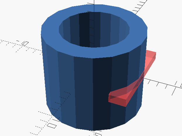
The rotate_extrude() command operates on 2d shapes by extruding them around the Z-axis. To create a rotated extrusion in another axis apply a transformation after the rotate_extrude operation.
To create an extrusion first create a 2d shape. We will use a square.
square([2,10], center = true)
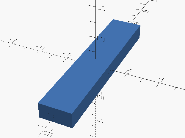
To get the pipe shape we will move the square 5 units on the X axis.
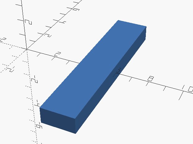
A simple way to image the revolve is, when you have the 2d object in view, image the X axis will end up as the Z axis and the rotation will occur counterclockwise when looking from above.
First OpenSCAD will orient the 2d Shape to the Z-Axis
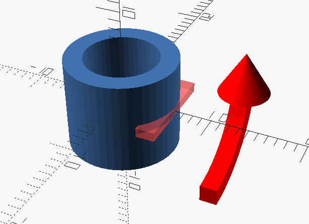
Then OpenSCAD will revolve the shape around the Z-Axis.
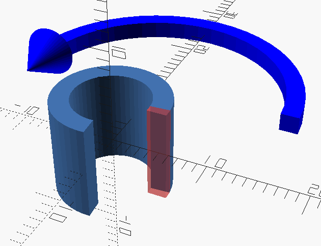
To create a revolve that only travels a portion of the revolve arc use the angle keyword
rotate_extrude( angle=270)
translate([5,0,0])
square([2,10], center=true);
rotate_extrude but i was trying to understand what the ‘convexity’ variable is all about!?
Convexity, as far as I understand it, is the number of polygons on any given line. What that means is, that if you draw a line, how many polygons will it pass through.
So for example if I have a solid cylinder, the most polygons ( could be interpreted like: surface/plane/wall ) the line will pass through is 2. However, if the cylinder is a tube the MOST a random line will pass through is 4. The line would pass through the outer wall once, inner wall once, inner wall a second time, outer wall a second time.
Setting convexity to 10 seems to account for most shapes.
This setting is mostly for rendering.
“First OpenSCAD will orient the 2d Shape to the Z-Axis”
Why such a counter intuitive behavior?
You would have to ask the developers. It took me awhile to understand this and is exactly the reason I included it in the post 🙂
because rotate_extrusion was originally designed for flat 2D polygons, like square, circle, etc, not a cube. and flat polygons are ALWAYS drawed in the xy plane. that’s the reason that, internally, rotate_extrusion does a x-axis 90 degree rotate first, to put the 2D figure parallel to z axis.
Then perhaps it should extrude around the X-axis or Y-axis instead of the Z-axis? Why did the developers insist on extruding around the Z-axis?